Test & Measurement
Megger MIT300 vs BM5200: Choosing a Small Multimeter, C5 Thermal Camera, or IFM Sensors by Scenario
-
The mistake that made me stop guessing
-
Scenario 1: The live circuit and the small multimeter
-
Scenario 2: Routine insulation testing on low-voltage machines
-
Scenario 3: Medium-voltage cables and 5 kV diagnostic tests
- Scenario 4: Problems that hide until they cause downtime
-
How to tell which scenario you are in
The mistake that made me stop guessing
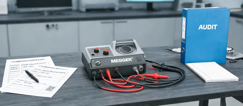
I'm not going to tell you there is one perfect insulation tester. That would be dishonest. In my first year handling instrument orders for a maintenance group, I treated the Megger MIT300 insulation tester and the Megger BM5200 5k insulation tester as two versions of the same product. They are not. Both are insulation testers, but the test voltage difference is the whole point: the MIT300 is for routine low-voltage work, while the BM5200 is a 5 kV instrument for more demanding insulation tests.
The mistake cost us two days and a rental fee. We caught the problem before anyone connected the leads, but the job still stopped while we found the right tool. Since then I start with three questions: Is the circuit live or de-energized? What is the system voltage? What failure am I trying to find?
Scenario 1: The live circuit and the small multimeter
If you need to check whether 24 V is reaching a PLC input, whether a fuse is open, or whether a sensor output is switching when metal passes, what you need is a small multimeter. This is the first branch of my decision tree.
A small multimeter is not a toy. Before I buy one, I check for a CAT rating printed on the meter. If it does not state an overvoltage category, I will not take it near an industrial panel. The size helps me carry it everywhere, but the safety rating decides whether it is allowed to leave the office.
Here is the boundary: a small multimeter is not a substitute for an insulation tester. Multimeters measure continuity and resistance using a very low voltage. Insulation breakdown often only appears when you apply a real test voltage. So the meter stays in my pocket for live circuit checks, and the insulation tester gets used only on de-energized equipment.
Scenario 2: Routine insulation testing on low-voltage machines
The tool that belongs in this scenario is the Megger MIT300 insulation tester. It is my baseline for motors, cables, and control transformers that operate below 1,000 V.
Why not the BM5200? Because a 5 kV tester is overkill on a 400 V motor. It costs more, it weighs more, and the higher test voltage can create an unnecessary problem on equipment designed for low voltage. The MIT300 gives you the insulation test range you need for routine low-voltage work without turning every oilfield or factory floor into a high-voltage lab.
Again, the machine must be de-energized and isolated before you connect the test leads. If you need to make live checks, you are back in small multimeter territory. Don't blur those lines.
Scenario 3: Medium-voltage cables and 5 kV diagnostic tests
Once you move above 1,000 V, the MIT300 may not be enough. Medium-voltage feeder cables, large motors, and switchgear can develop insulation weaknesses that a 1,000 V tester will not stress the same way. That is when I request the Megger BM5200 5k insulation tester.
The 5 k in the model name matters. The BM5200 can apply up to 5,000 V DC, which lets the test get closer to the stress the insulation will see in service. If your procedure calls for polarization index, step voltage, or timed insulation tests, a 1 kV tester simply will not give you the answer.
Here is the honest part: if you only test medium-voltage cable twice a year, renting a BM5200 or using a contractor who performs these tests regularly may make more sense than owning one. I would rather admit that than sell someone a tool that sits in a case. The expert who knows the limit of their everyday gear is more reliable than the one who pretends every job is the same.
Scenario 4: Problems that hide until they cause downtime
Use a C5 compact thermal imaging camera for heat patterns
Not every fault shows up as a voltage or resistance value. Some faults show up as heat. A C5 compact thermal imaging camera has become my second pair of eyes for switchgear, terminal blocks, motor casings, and busbar connections.
The thermal camera does not replace an insulation tester. It finds the spot that deserves a closer look. A loose connection can look fine and still be hotter than the connection beside it. When the thermal image shows a clear hotspot, I plan a shutdown, tag the equipment out, and then confirm the cause with the right electrical test. That sequence is what separates survey from diagnosis.
How to install IFM inductive sensors step by step
Sensor installation is another early-warning issue. A machine might stop intermittently because a proximity sensor was mounted without enough clearance from surrounding metal. I have lost more time to sensors installed wrong than to sensors that were actually bad.
Here is how to install IFM inductive sensors step by step based on my current checklist:
- Turn off the supply before wiring. Inductive sensors can be damaged by live wiring, and the PLC input is not always protected against mistakes.
- Confirm whether the sensor is flush or non-flush. Flush types can be mounted with metal around the active face. Non-flush types need metal-free space around the sensing face, or the surrounding metal can interfere with the detection field.
- Connect the wires correctly. Don't hold me to this without checking the sensor label, but the standard three-wire DC colors are brown for positive, blue for negative, and black for the normally open output. With an M12 connector, pin 1 is positive, pin 3 is negative, and pin 4 is the output.
- Set the sensing distance with the actual metal target. Inductive sensors only detect metal. The target must be inside the rated operating distance and larger than the minimum target size listed for that sensor.
- Test the output with a small multimeter before connecting it to the PLC. If the sensor is PNP, the output should switch to supply voltage when the target is present. If it is NPN, the output should switch toward 0V. Match that to what your PLC input expects.
- Mount the sensor with the provided nuts and do not twist the sensor body to align the cable. Then lock the nuts so vibration cannot move it.
Different IFM sensor families have different options, including IO-Link and two-wire versions. The step that never changes is verification: check the datasheet, check the surrounding metal, and check the output with a meter before trusting it.
How to tell which scenario you are in
Still unsure? Write down three facts before you order or open the toolbox. Is the equipment live or de-energized? What is the system voltage? What are you trying to detect or avoid?
Then route yourself: live control panel questions go to a small multimeter. De-energized low-voltage insulation checks go to the Megger MIT300 insulation tester. Medium-voltage insulation diagnostics go to the Megger BM5200 5k insulation tester. Heat patterns go to a C5 compact thermal imaging camera. Metal presence and machine position go to the IFM inductive sensor installation checklist.
If you ask me, the best suppliers are willing to say, this is not the right tool for that job. I would rather rent a 5 kV tester for one important test than own one that never leaves the shelf. The same principle applies to installation guides: don't follow generic advice when the datasheet and the application both matter. That is what separates advice from a real answer.

Marcus Feld
Marcus Feld is an electrical test and measurement analyst specializing in multimeters, oscilloscopes, clamp meters, insulation testers, spectrum analyzers, and data loggers. He applies IEC 61010-2-030 and IEC 61010-031 concepts while examining measurement category, bandwidth, true-RMS response, input loading, and stated uncertainty. His work helps maintenance engineers and test teams choose safe instruments with performance suited to the signals and environments they actually measure.