Test & Measurement
Megger, 381 Clamp Meter, E8 Pro Thermal Camera, or Tektronix Scope? Let the Test Decide
-
First, Which Question Are You Asking?
- Scenario A: Is the Insulation Safe? Bring Out the Megger Insulation Tester
-
Scenario B: How Much Current Is Flowing? The 381 Clamp Meter
-
Scenario C: Where Is That Heat Coming From? E8 Pro Thermal Imaging Camera
-
Scenario D: Why Is the Waveform Wrong? How to Use Tektronix Oscilloscope
-
How to Decide Which Scenario You Are Actually In
Every week, someone asks me which test instrument they should buy: a megger insulation tester, a 381 clamp meter, an E8 Pro thermal imaging camera, or a Tektronix oscilloscope. Most people expect me to name one winner.
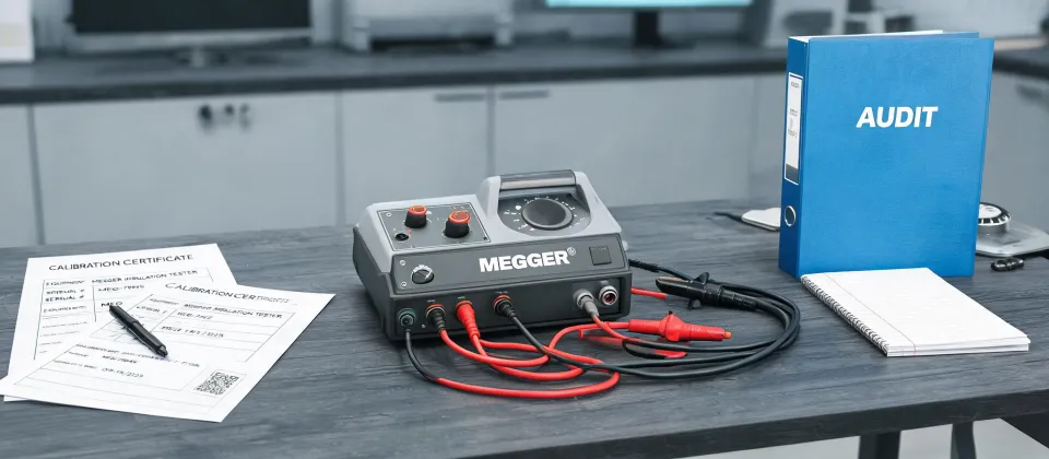
I'm not going to do that. The right tool depends on the failure you're looking for, not on which brand is popular this quarter. I'm a quality/compliance manager at a test and measurement supplier, and I review roughly 200 unique instruments per year before they go out the door. If the calibration certificate doesn't match the serial number, I reject it. If the CAT rating label can't be supported by the meter's design, I reject it. That background has made me suspicious of one-size-fits-all recommendations.
Here is the framework I use: sort yourself by the question you're asking, not by the equipment category.
First, Which Question Are You Asking?
- Is the insulation still healthy enough to energize? That puts you in the megger insulation tester scenario.
- How much current is flowing in this conductor while it is live? That is what a 381 clamp meter is for.
- Where is that heat coming from? That's where the E8 Pro thermal imaging camera belongs.
- Why is this waveform doing that? Now it's time to understand how to use Tektronix oscilloscope.
Scenario A: Is the Insulation Safe? Bring Out the Megger Insulation Tester
A megger insulation tester is not a normal ohmmeter. It is a controlled high-voltage source and a current meter. When you press Test, it applies a DC voltage between its Line and Earth terminals and measures the tiny current leaking through the insulation. The meter displays that leakage as a resistance value in megohms. High leakage means a lower displayed resistance.
That's also why you can't substitute a digital multimeter's resistance range for this test. A regular meter uses too low a voltage. It will miss insulation weak spots that only show up under similar voltage stress to what the equipment will see in service.
Megger Insulation Tester Diagram, In Plain Words
The classic megger insulation tester diagram is simple, even though the instrument inside is not. The Line terminal connects to the conductor under test. The Earth terminal connects to ground, to the motor frame, or to another conductor. An internal DC generator or electronic converter supplies the test voltage. The current that leaks through the insulation returns to the meter and moves the reading.
The Guard terminal is the part people tend to ignore. It creates a separate return path for surface leakage. If you test a cable with dust or moisture on the terminal block, surface leakage can travel across that contamination and make the insulation look worse than it actually is. Connect Guard to the surface you want to exclude, and the meter can ignore most of that leakage.
How to Use Megger Insulation Tester
- Establish an electrically safe work condition. NFPA 70E uses that phrase for a reason: disconnect, lock out, verify zero voltage with a DMM, and only then connect the megger.
- Isolate sensitive electronics. If the cable or motor is connected to a VFD, PLC, or surge protection, disconnect those components first. The megger output can damage electronics even at test voltages that are perfectly safe for the motor.
- Select the test voltage. For most 480/600 V class equipment, 500 V or 1000 V is typical. For higher voltage switchgear, you may need 2500 V or more. Check the equipment manufacturer's recommendation when one exists.
- Connect the leads. Line goes to the conductor under test, Earth goes to ground or frame, and Guard goes where surface leakage is a risk.
- Run the test and record the reading after 60 seconds, not as soon as the display stops moving.
- Discharge the circuit before disconnecting. The cable can hold a charge for a while after the test. Let the meter discharge it through its internal circuit before you pull the leads off.
One honest disclaimer: I don't have hard data on how many returned insulation testers are actually setup errors. But based on the units I see in receiving, my sense is that a large share of them could have been avoided by a slower and safer setup.
Here's a slightly unpopular opinion: for simple go/no-go insulation checks, I'd rather use a dedicated megger with one test voltage knob than an all-in-one instrument with a long menu. When high voltage is active, you don't want to go through three screens to find the Stop button.
Scenario B: How Much Current Is Flowing? The 381 Clamp Meter
If the circuit is live and you need to know the load current without opening the circuit, a clamp meter is the practical answer. The clamp jaw measures the magnetic field around a single conductor. No series connection is needed, so you can keep the circuit running while you gather data.
The term 381 clamp meter is less specific than it sounds. Different brands use similar numbers, and the exact current range, jaw size, and CAT rating matter. The one I'm most familiar with is a true-RMS AC/DC current meter with a fairly large jaw, but I don't remember every revision. That's not a hesitation—that's a quality manager telling you to verify the nameplate before you trust it.
To use one properly:
- Set the function to AC current, or AC/DC if your circuit has a DC component.
- Clamp around only one conductor. If you clamp around two wires feeding the same load, the currents cancel and you'll read zero or meaningless numbers.
- Center the conductor inside the jaw and close the jaw fully.
- For small DC currents, press the zero button and keep the lead steady while reading.
- If you are checking motor starting current, look for an inrush or MIN/MAX mode.
It's tempting to think of a clamp meter as a multimeter with a big handle. That misses the point. The main advantage is that you don't have to break the circuit, which means you can troubleshoot a live panel more quickly and with fewer steps.
But don't try to test insulation with a clamp meter. It reads current flowing in a live conductor. It can't tell you whether a motor winding will hold up at 1000 V DC. That's still the megger's job.
Scenario C: Where Is That Heat Coming From? E8 Pro Thermal Imaging Camera
The E8 Pro thermal imaging camera is a different kind of tool. It doesn't measure electrical current or insulation resistance. It measures temperature patterns across a surface, which makes it excellent for finding loose connections, overloaded conductors, and failing contacts before they turn into equipment damage.
Back in 2022, I second-guessed spending money on our first thermal camera. I convinced myself that a contact thermometer would be good enough. Then the camera found a B-phase lug running almost 30 degrees hotter than the other two phases inside a breaker panel. The connection was already discolored. That one inspection paid for the camera.
To get genuinely useful thermal images:
- Put a realistic load on the circuit. A loose connection only heats up when current is flowing. A cold panel at 2 a.m. tells you very little.
- Set an appropriate emissivity. Painted metal and cable insulation are close to 0.95, but shiny bare copper and aluminum reflect their surroundings and can trick the camera.
- Focus carefully. An out-of-focus thermal image may look colorful, but the measurement is not reliable.
- Use manual level and span when comparing two similar panels. Autoscale can make every image look dramatic; manual settings let you compare apples to apples.
The E8 Pro is not an alternative to a megger insulation tester. A thermal camera sees heat caused by current and resistance. It cannot see insulation degrading inside a motor winding until the leakage has already become severe enough to produce heat. If you want early warning on insulation health, use the megger. If you want to find the hot connection before it fails, use the thermal camera. You need both in different scenarios.
Scenario D: Why Is the Waveform Wrong? How to Use Tektronix Oscilloscope
An oscilloscope answers a very different question: what is this signal doing over time? That's why you reach for a scope when a multimeter reading looks fine but the equipment still misbehaves.
A 24 V control signal can show 24 V on a meter while the actual waveform is so full of noise or dropouts that the PLC can't read it reliably. A VFD output can look close to the right voltage but have distorted switching edges that cause motor problems. Those are oscilloscope problems.
I get why oscilloscopes look intimidating. The front panel has a lot of controls. But Tektronix scopes share the same basic logic as most scopes: think in terms of vertical, horizontal, and trigger.
To get started on any Tektronix scope:
- Check the probe switch. If the probe is set to 10x, tell the channel that the probe is 10x. If you forget this, every voltage measurement will be off by a factor of ten.
- Connect the probe tip to the signal and the ground clip to a safe ground reference. Do not connect the ground clip to a high-voltage live point unless you are using an isolated or differential probe.
- Set the vertical scale so the expected signal fits on the screen. For a 5 V logic signal with a 10x probe, you might start at around 1 V or 2 V per division.
- Set the horizontal time base based on the signal's speed. For a 50 or 60 Hz power waveform, try 2 ms per division. For fast digital signals, adjust from there.
- Set the trigger. Choose your input channel as the trigger source, use an Edge trigger with rising slope, and set the trigger level near the middle of the waveform.
- Press Auto, then adjust the trigger level until the trace stops scrolling. Use Run/Stop if you need to freeze a single event.
Tektronix's own XYZs of Oscilloscopes primer is worth reading before you go much deeper. It explains why the vertical system, horizontal system, and trigger all matter. If you search online for how to use Tektronix oscilloscope, that guide is one of the first things that deserves your attention.
A common mistake is skipping the trigger setup and letting Autoset handle everything. Autoset can produce a nice trace, but it may hide the event you're chasing. When you're hunting an intermittent problem, the trigger is your friend.
How to Decide Which Scenario You Are Actually In
If you're still not sure which tool belongs on your bench, ask what decision the reading will change.
- If the equipment is off and your question is whether the insulation will hold up under high voltage, choose a megger insulation tester.
- If the equipment is live and you need to measure load current without breaking the circuit, choose a 381 clamp meter.
- If you're inspecting connections, breakers, and loaded conductors for heat, choose an E8 Pro thermal imaging camera.
- If you're chasing waveform shape, timing, noise, or glitches, choose a Tektronix oscilloscope.
If the measurement won't change what you do next, don't spend the money yet. One good megger in the hands of someone who uses it correctly is worth more than a shelf of gear that mostly collects dust.
That last point matters for small orders too. It's easy for a one-person shop or a startup lab to feel awkward about buying just one meter. Don't. A $300 order deserves the same calibration documentation and support as a $30,000 order. The instrument doesn't know how much it cost. And a supplier that treats small orders like interruptions today will probably forget you tomorrow when your needs grow.
So don't ask which tool is better. Ask which failure you're trying to find. That turns the vague phrase it depends into a concrete answer.

Marcus Feld
Marcus Feld is an electrical test and measurement analyst specializing in multimeters, oscilloscopes, clamp meters, insulation testers, spectrum analyzers, and data loggers. He applies IEC 61010-2-030 and IEC 61010-031 concepts while examining measurement category, bandwidth, true-RMS response, input loading, and stated uncertainty. His work helps maintenance engineers and test teams choose safe instruments with performance suited to the signals and environments they actually measure.